| Ⅰ. Application |
| Able to accurately simulate a wide range of complicated natural environments, and is suitable for reliability test in industrial products. Meet GB5170.2.3.5.6-95 standard requirements of environmental testing equipment and test methods for the basic parameters of electric and electronic products under the condition of humidity, low temperature, high temperature, and constant heat. |
| Ⅱ. Application |
| Applicable to environmental adaptability and reliability test in such industrial units as electronics, electrical appliance, battery, plastics, food, paper product, vehicle, metal, chemistry, building material, research institution, inspection and quarantine bureau, university etc.. |
| Ⅲ. Features |
|
● GB-2423. 1-89(IEC68-2-1)Test A: Low Temperature Test
● GB-2423. 2-89(IEC68-2-2)Test B: High Temperature Test
● GJB360. 8-87(MIL-STD. 202F) High Temperature Life Test
● GBJl50. 3(MIL-STD-810D) High Temperature Test
● GJBl50. 4(MIL-STD-810D) Low Temperature Test
● GB2423. 3-93(IEC68-2-3)Test Ca: Constant Heat Test
● GB2423. 4-93(IEC68-2—30)Test Db: Damp Heat Alternative Test
● GJBl50. 9-93(MIL-STD-810D) Damp Heat Test
|
| 1.Energy-saving |
- Bypass mode to adjust cooling capacity to achieve a constant temperature and humidity effectively
- Apply plate exchanger as intermediate heat exchanger to the cascade refrigerating system, ensuring high effective.
|
| 2.Easy operation |
- Using company owned brand KOMEG KM-5166 LCD touch screen controller with PID control parameters setting;
- Flexible approach for data collection and recording
|
| 3.High reliability |
- Key parts are imported to ensure service life and high reliability
- High effective oil separator ensuring the service life of compressor.
- Using Reverse Osmosis (RO) Water Purifier to ensure long service life of humidifying electric heater
|
| Ⅳ.Main Technical Index |
| 1. Body |
| 1.1 Workplace volume |
IW 1500 × IH 2000 × ID 200 mm about 6 m³ |
|
1.2 External dimensions
|
IW 3050 × IH 2410 × ID 2200 mm |
| 2. Temperature |
| 2.1 Temp. range |
-50℃~150℃ |
| 2.2 Temp. deviation |
≤±2.0℃ |
| 2.4 Temp. fluctuation |
±0.5℃ |
| 2.5 Temp. uniformity |
≦2.0℃ |
| 2.5 Heating and cooling rate |
-50℃↓ +150℃ temperature change rate non-linear 2℃/min (no load)
+150℃ ↑ -50℃ temperature change rate non-linear 1℃/min(no load)
|
| Water-cooled. The above specifications measurement in the environment temperature at + 25 ℃ without load |
| 3. Humidity |
| 3.1 Humidity range |
20%R.H~98%R.H |
| 3.2 Humidity deviation |
±3.0%RH(>75%RH)
±5.0%RH(≤75%RH)
|
| 3.3Humidity fluctuation |
±3.0%RH (no-load) |
| 3.4 Humidity uniformity |
±2.0%RH |
| Water-cooled. The above specifications measurement in the environment temperature at + 25 ℃ without load |
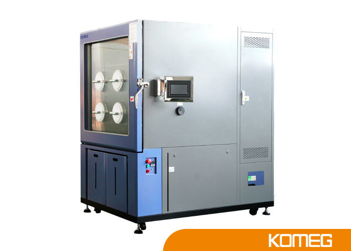
| Ⅴ. Body Structure |
|
Overall structure and chamber is composed of three parts as below.
Insulation box, separate refrigeration units, and electrical control cabinet.
|
| 1. Insulation Box |
Insulation preservation plate connected by eccentric hooks
Wall material: imported high-quality rolled steel sheet;
Inner wall material: not less than 0.6-0.8mm SUS304 stainless steel, corrosion resistant and easy to clean;
Insulation material: rigid polyurethane foam insulation layer
|
| 2. Door |
Single door, heating wire is installed at the door frames to prevent condensation at low temperatures |
| 3. Inspection Window |
With a H380mm×W500mm(for ref.) inspection windows installed on the door, multi-hollow electric insulation coated glass prevent condensation effectively |
| 4. Lighting Device |
1 PC 11W/AS220V installed in the inspection window |
| 5. Heating |
High quality nickel-chromium alloy wire electric heaters,
Non-contact control mode(SSR)
|
| 6. Humidifier |
Water basin heating and humidification method;
Stainless steel sheathed heater;
Heater control: no-contact control (SSR);
Water level control device, heater anti-dry device.
|
| 7. Water outlet hole |
Available for drain the condensate water |
| 8. Cable port |
φ100mm*1 located as close as floor with rubber stopper and stainless steel cover |
| 9. Shelf for samples |
No |
| 10. Mobile Casters |
Mobile Casters *4 with foot cups |
| 11. Electric control box |
Total power circuit breaker, over-temperature protection. |
| 12. Water supply system |
Water pump automatic supply |
| Ⅵ. Cooling System |
|
The refrigerating / dehumidification system applies a set of Germany Bock semi-hermetic cascade compressors.
Refrigeration methods can be classified into vapor compression refrigeration, absorption refrigeration, steam jet refrigeration, gas expansion refrigeration and thermoelectric refrigeration. Above all, vapor compression refrigeration is the most widely used and economical refrigeration method, and also is the most commonly method used in environmental testing equipment. The principle is using Freon and other liquid evaporation as the medium which absorbs and removes heat to achieve refrigeration.
Single-Stage refrigeration cycle diagram is the schematic diagram of vapor compression refrigeration cycle process.
|
|
1. Working mode
|
Water cooling mechanical compression cascade refrigeration |
| 2. Compressor |
Germany Bock Semi-hermetic Compressor with low noise |
| 3. Evaporator |
Fin-type multi-stage automatic load capacity adjustment, No frost in long-term use of low temperature and humidity conditions |
| 4. Condenser |
Shell and Tube condenser(Water-cooled) |
| 5. Refrigerant |
Environmental-friendly refrigerant: R404A,R23 |
| 6. Other accessories |
Use internationally-known brand, such as high precise expansion valve, oil extractor, dryer and many other accessories. |
| 7.Refrigerant flow control |
Adjust energy consumption output and control automatically to the refrigeration system. |
| 8.Refrigeration Technology |
※ Nitrogen welding, two-stage rotary vane vacuum pump, ensure that the internal cooling system clean and reliable.
※water tray located at the bottom of the compressor to ensure condensate water drain through pipe freely at the rear of the chamber.
|
| 9. Cooling mode |
Water-cooled shell and tube;
Air-cooled copper tube aluminum fins
|
|
10. Parts Brand
|
| Parts |
Brand |
Remarks |
| Compressor |
Germany Bock |
|
| Oil extractor |
EMERSON,ALCO,AC&R,ESK |
|
| Plate heat Exchanger |
Xinsuneng |
| Press replay |
DANFOSS or
RANCO
|
|
| Condenser |
Guangzhou Yongqiang |
|
|
Evaporator
|
Guangzhou Yongqiang |
|
|
Dry filter
|
DANFOSS
SPORLAN
|
|
| Capillary |
KOMEG |
|
| Expansion valve |
DANFOSS
SPORLAN
|
|
|
Electromagnetic valve
|
SAGINOMIYA
DANFOSS
|
|
| Note: Two options listed above are for customers’ choice and back up purpose. |
|
| Ⅶ. Control System |
| 1. Temp. &Humidity Tester |
High precision DIN class A, dry ball φ4.8mm SUS # 304 PT 100Ω. |
| 2. Controller |
KOMEG Technical Programmable KM-5166 TFT Touch Screen Controller with PID control
|
| 3. Display function |
Temp.& humidity Setting (SV) Practical (PV) value can be displayed directly
Execution of the program can display numbers, paragraphs, remaining time and cycles, running time display,
Program editing and graphic curve display,
Fixed or program operation status display,
7-inch TFT display screen.
|
| 4. Display resolution |
Temperature: + 0.01℃; Humidity: + 0.1%; Time: 1min. |
| 5. Setting range |
Temperature can be adjusted based on the working temperature of the equipment (the upper limit:+5℃, the lower limit:-5℃)
Temperature condition:-100~200℃
Humidity condition:0~100 %RH
|
| 6. Operating mode |
Programmable running, constant running and booking boot |
| 7. Set way |
Touch Mode Input |
| 8. Interface |
Data collection and curve display when connected with a computer
Can be used as monitoring and remote control system
Multi machines synchronization control available
|
| 9. U Disk Memory Card |
1G-8G available for downloading historical curve and data, pluggable |
| 10. Record way |
RAM with battery protection, setting (SV), Practical(PV) and sampling time can be saved;
Maximum historical data and curve memory storage is 90 days (when the sampling time is 1 min)
|
| 11.Power off memory |
Power recovery mode can be set as hot start, cold start and stop |
| 12. Pre-set function |
Boot time can be set freely and machine runs automatically when turning on power |
| 13. Software environment |
Windows2000 or Windows XP operating system |
| 14. Network Connection |
Can be connected to Ethernet via professional software,
Remote control & assistance function and data collection can be achieved through network,
Multi machine can be controlled simultaneously
|
| 15. Date and time |
Fault alarm and cause handling prompts, power failure protection, the temperature upper and lower limit protection, timer function (automatic start and automatic stop running), self-diagnostic function. |
| Ⅷ.Electrical Control System |
| 1.Control cabinet |
A. Emergency stop switch
B. Power switch
C. Over-temperature protection
D.RS-485 interface
|
|
2. Protection System
|
A. Heater protection switch if no water
B. Humidifier protection switch if no water
C. Heater over-current circuit breaker
D. Humidifier over-current circuit breaker
E. Circulating fan over-current overload protection
F. Compressor high voltage protection switch
G. Compressor overheat protection switch
H. Compressor over-current protection switch
I. Over-voltage under-phase protection switch
J. Circuit Breakers
K. Leakage switch
L Low humidifier protection
M. Water tank low water level warning
Controller noise isolation protection
O. Zero-crossing gate fluid power controller
|
|
2. Parts brand
|
| Parts |
Brand |
Remarks |
| Controller |
KOMEG |
KOMEG Technical Programmable KM-5166 |
| Breaker |
Schneider |
|
| AC contactor |
Fuji
Schneider
|
|
| Thermal relay |
Schneider |
|
| Phase sequence relay |
Carlo Gavazzi |
|
| Time relay |
Autonics
OMRON
|
|
| AC relay |
Schneider |
|
| Solid relay |
Carlo Gavazzi |
|
| Note: Two options listed above are for alternate choice and backup purpose. |
|
| 4. Alarm indicator |
Equipment stops running and sends audible alarm when the above protection appears, meanwhile, fault, causes and solutions will be displayed on the screen. |
| Ⅸ. Installment & Using Condition |
| 1. Ambient temp. and humidity |
5 ~ 35℃ |
| 2. Air quality |
No high concentrations of dust or corrosive gases |
| 3. Installation site requirements |
Distance from the wall to both sides and rear of the chamber should be more than 800mm, to the front more than 1500mm.
Users should provide independent distribution gear and humidification condensate drains, and external power connector device is necessary.
Ground level, well-ventilated, non-flammable, explosive, corrosive gas and dust
No strong electromagnetic radiation nearby
With floor drain (less than 2 meters from the refrigeration unit)
Venue floor load capacity: not less than 500KG/㎡
Leave adequate space for maintenance.
|
| 4. Grounding |
Grounding resistance≦4Ω, grounding bolts located on the base of the cabinet |
| 5. Water draining |
Drain hole located at the base of the cabinet |
| 6. Cable port |
φ50,φ80,φ100,φ120mm cable port, location and number can be customized according to user requirements under if the chamber body structure allows. |
|
7. Storage
environment
|
The ambient temperature should be maintained within 0~45℃ when the equipment doesn’t work.
Drain out the remaining water in the equipment to avoid pipe freezing and broken when the ambient temperature is below 0 ℃.
|
|
8. Centralized
monitoring
|
For remote centralized monitoring, need another PC (Windows 2000/XP operating system, a com port and USB port). |
| 9. Power |
AC 3ψ4W 380V 50Hz (R, S, T, N plus ground) (voltage fluctuation ≦ ± 10%) |
|
P.S.
1. Please equip the above power demanded to the terminal box of the machine control, user must prepare an exclusively no-fuse switch for the machine.
2. The above water source demand to match to the host machine and connected the host.
3. The above compressed air source demand to match to the host machine and connected the host.
4. Please confirm whether it can enter the door or access elevators.
5. This offer is only the price of the machine, do not contain power cord outside the machine, gas supply, cooling towers and piping engineering cost.
|
| Ⅹ. Technical Documentation |
| 1. Technical documentation |
※Operational Manual*1
※Maintenance Manual*1
|
 Your message must be between 20-3,000 characters!